Back to Contents Page
Dell™ PowerEdge™ 2550 Systems Installation and Troubleshooting Guide
This section provides troubleshooting procedures for components inside the system. Before you start any of the procedures in this section, take the following steps:
You need the following items to perform the procedures in this section:
- The system's User's Guide
- The Dell OpenManage Server Assistant CD and several blank, formatted 3.5-inch diskettes. (If you cannot run the Dell™ Diagnostics from the utility partition on your system's hard-disk drive, you can create a set of diagnostics diskettes using the Dell OpenManage Server Assistant CD. See your system's User's Guide for additional information about using the Dell OpenManage Server Assistant CD.)
- The key to the system keylock
 |
NOTE: When you see the question "Is the problem resolved?" in a troubleshooting procedure, perform the operation that caused the problem. |
The procedures in this guide require that you open the computer doors and work inside the computer. While working inside the computer, do not attempt to service the computer except as explained in this guide and elsewhere in Dell documentation. Always follow the instructions closely.
 |
WARNING: FOR YOUR PERSONAL SAFETY AND PROTECTION OF THE EQUIPMENT |
|
WARNING: Before starting to work on the computer, perform the following steps in the sequence listed: |
- Turn off and disconnect your computer and peripherals from their power sources (unless you are installing or removing a hard-disk drive). Also, disconnect any telephone or telecommunication lines from the computer.
- Ground yourself by touching an unpainted metal surface on the chassis, such as the metal around the card-slot openings at the back of the computer, before touching anything inside your computer.
- While you work, periodically touch an unpainted metal surface on the computer chassis to dissipate any static electricity that might harm internal components.
In addition, Dell recommends that you periodically review the safety instructions in the System Information document provided with your computer.
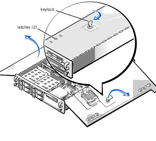
The system has two doors on the top of the system that provide access to the system board and expansion cards. The doors interlock so that the keylock on the right-side door secures both doors.
To open the system doors, perform the following steps:
- Observe the precautions in "Safety First—For You and Your Computer" found earlier in this section. Also observe the safety instructions in the System Information document.
- Slide the system out of the rack.
- Using the system key, turn the keylock on the top of the chassis to the unlocked position (see Figure 7-1).
- Press the two latches to release the right door (see Figure 7-1).
- Lift the right door.
- Lift the left door.
When closing the doors, be sure to close the left door first and then the right door.
Figure 7-1. Opening the System Doors
You must remove the system's front bezel before installing or removing a hard-disk drive or using the diskette or CD-ROM drive.
To remove the front bezel, perform the following steps:
- Unlock and open the system doors (see "Opening the System Doors").
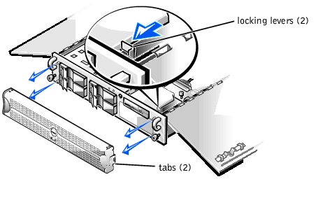
- Pivot the two locking levers towards the front of the chassis (see Figure 7-2).
- Press the tab on each end of the bezel and remove the bezel from the chassis (see Figure 7-2).
Figure 7-2. Removing the System Bezel
Your Dell system has a removable expansion-card cage, which simplifies many installation procedures by allowing you to remove the riser board and all installed expansion cards in a single step.
To remove the expansion-card cage, perform the following steps:
- Turn off the system, including any attached peripherals, and disconnect the system from the electrical outlet.
|
WARNING: See "Protecting Against Electrostatic Discharge" in the safety instructions in your System Information document. |
- Open the system doors (see "Opening the System Doors").
- Check any cables connected to expansion cards through the back-panel openings. Disconnect any cables that will not reach to where the cage must be placed upon removal from the chassis.
|
NOTE: To prevent damage to the system board or riser board, verify that the power LED on the riser board (see Figure 7-3) is off before removing the expansion-card cage. |
Figure 7-3. Removing the Expansion-Card Cage
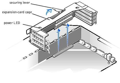
- Locate the expansion-card cage securing lever (see Figure 7-3), and rotate the lever upward until it stops in an upright position.
- Lift the expansion-card cage up and away from the chassis.
To replace the expansion-card cage, perform the following steps:
- With the securing lever in the upright position, lower the expansion-card cage into place until it is aligned.
- Rotate the securing lever downward until it is flush with the top of the chassis. Make sure that the riser board is fully seated in the RISER connector on the system board.
- Reconnect any cables you removed in step 3 of the previous procedure, "Removing the Expansion-Card Cage."
In Figure 7-4, the system doors are open to provide an interior view. Refer to this illustration to locate interior features and components discussed later in this guide.
Figure 7-4. Inside the System
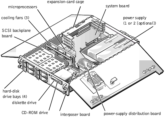
The system board holds the system's control circuitry and other electronic components. Several hardware options, such as the microprocessors and memory, are installed directly on the system board. The expansion-card cage accommodates up to three full-length Peripheral Component Interconnect (PCI) expansion cards. The two peripheral bays provide space for a 3.5-inch diskette drive, CD-ROM drive, and an additional 5.25-inch device such as a tape drive.
The hard-disk drive bays provide space for up to four 1-inch small computer system interface (SCSI) hard-disk drives. These hard-disk drives are connected to a SCSI host adapter on the system board or on an expansion card, via the SCSI backplane board.
The power cables leading from the power-supply distribution board (PSDB) provide power to the system board, SCSI backplane board, and drives in the peripheral bays.
For non-SCSI drives such as the diskette drive and CD-ROM drive, an interface cable connects each drive to the interposer board or to an expansion card. For SCSI devices, interface cables connect the SCSI backplane board to a SCSI host adapter on the system board or on an expansion card. For more information, see "Installing a Drive in the Peripheral Bay" and "Installing Hard-Disk Drives."
During an installation or troubleshooting procedure, you may be required to change a jumper or switch setting. For information on the system board jumpers, see Appendix A, "Jumpers, Switches, and Connectors."
Liquid spills, splashes, and excessive humidity can cause damage to the system. If an external device (such as a printer or an external drive) gets wet, contact the device manufacturer for instructions. If the system gets wet, perform the following steps:
- Turn off the system, including any attached peripherals, and disconnect the system from the electrical outlet.
|
WARNING: See "Protecting Against Electrostatic Discharge" in the safety instructions in your System Information document. |
- Open the system doors (see "Opening the System Doors").
- Let the system dry for at least 24 hours.
Make sure that the system is thoroughly dry before proceeding.
- Remove all expansion cards installed in the system.
- Close the system doors, reconnect the system to the electrical outlet, and turn on the system.
Does the system have power?
Yes. Go to step 6.
No. See "Getting Help" for instructions on obtaining technical assistance.
- Turn off the system, disconnect it from the electrical outlet, open the system doors, and reinstall all expansion cards you removed in step 4.
- Close the system doors and reconnect the system to the electrical outlet.
- Run the Dell Diagnostics and test the system.
Did the tests run successfully?
Yes. The system is operating properly.
No. See "Getting Help" for instructions on obtaining technical assistance.
If the system was dropped or damaged while being moved, you should check the system to see if it functions properly. If an external device attached to the system is dropped or damaged, contact the manufacturer of the device for instructions or see "Getting Help" for information on obtaining technical assistance from Dell.
To troubleshoot a damaged system, perform the following steps:
- Turn off the system, including any attached peripherals, and disconnect the system from its electrical outlet.
|
WARNING: See "Protecting Against Electrostatic Discharge" in the safety instructions in your System Information document. |
- Open the system doors (see "Opening the System Doors").
- Check the following connections:
- Expansion-card connections to the expansion-card cage
- Drive carrier connections to the SCSI backplane board
- Verify all internal cable and component connections.
Make sure that all cables are properly connected and that all components are properly seated in their connectors and sockets. Pay particular attention to the interposer board and PSDB (if installed).
- Close the system doors and reconnect the system to the electrical outlet.
- Run the system board tests in the Dell Diagnostics.
Did the tests run successfully?
Yes. The system is operating properly.
No. See "Getting Help" for instructions on obtaining technical assistance.
If an error message indicates a problem with the battery or if the System Setup program loses the system configuration information when the system is turned off, the battery may be defective.
To troubleshoot the battery, perform the following steps:
- Turn off the system, including any attached peripherals, and disconnect the system from its electrical outlet.
|
WARNING: See "Protecting Against Electrostatic Discharge" in the safety instructions in your System Information document. |
- Open the system doors (see "Opening the System Doors").
- Check the connection of the coin cell battery to the system board.
See "Replacing the Battery" in "Installing System Board Options" for information on gaining access to the battery socket.
- Is the battery firmly installed in the battery socket on the system board?
Yes. Go to step 7.
No. Go to step 6.
- Reseat the battery in its socket.
- Close the system doors and reconnect the system to the electrical outlet.
Is the problem resolved?
Yes. The battery was loose. You have fixed the problem.
No. Continue with this procedure.
 |
CAUTION: There is a danger of a new battery exploding if it is incorrectly installed. Replace the battery only with the same or equivalent type
recommended by the manufacturer. Discard used batteries according to the manufacturer's instructions. |
- Repeat steps 1 and 2.
- Replace the battery.
Is the problem resolved?
Yes. The battery's charge was low. You have fixed the problem.
No. See "Getting Help" for instructions on obtaining technical assistance.
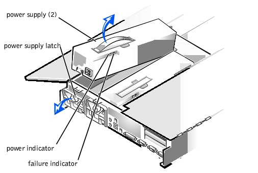
Your system may contain two optional, redundant power supplies. The two indicators on the back of each power supply (see Figure 7-5) signal the power supply's current status. If the red (forwardmost) failure indicator lights up, replace the power supply as described in the following procedure.
Figure 7-5. Power Supply Features and Removal
To replace a power supply, perform the following steps.
|
WARNING: The power supply is heavy. Support it with both hands when installing or removing it. |
- Turn off the system, including any attached peripherals, and disconnect the system from its electrical outlet.
- Unplug the AC power cable from the faulty power supply.
|
WARNING: See "Protecting Against Electrostatic Discharge" in the safety instructions in your System Information document. |
- Open the system doors (see "Opening the System Doors").
- Remove the power supply:
- The power supply is secured by a latch on the back panel of the system.
Rotate the top of the power supply latch downward.
- Grasp the handle on the top of the power supply and lift the power supply straight up from the system.
- Lower the new power supply into the chassis.
- Close the power supply latch.
|
NOTE: The power supply will not function until the latch is engaged. |
- Close the system doors.
- Connect the AC power cable to the new power supply.
Three cooling fans are installed in the system chassis. (Fan 1 is the outermost fan in the fan assembly.) If you observe that one of the cooling fans is not operating or if the server management application issues a fan-related error message, perform the following steps to troubleshoot the problem:
- Turn off the system, including any attached peripherals, and disconnect the system from its electrical outlet.
|
WARNING: See "Protecting Against Electrostatic Discharge" in the safety instructions in your System Information document. |
- Open the system doors (see "Opening the System Doors").
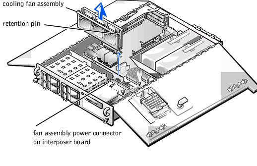
- Unplug the cooling fan wiring harness from the interposer board by pressing the release tab on the power cable connector.
- Loosen the fan assembly retention pin and lift the fan assembly out of the system (see Figure 7-6).
Figure 7-6. Removing the Cooling Fan Assembly
- To replace an individual fan, perform the following steps:
- Separate the two halves of the fan assembly by pressing the locking tabs at each end of the assembly.
- Remove the faulty fan and disconnect it from the cooling fan wiring harness.
- Install a new fan in the assembly and connect it to the fan power wiring harness.
- Join the two halves of the fan assembly.
- Slide the fan assembly back into the system and reinstall the retention pin.
When reinstalling the fan, be careful to avoid pinching the system interface cables.
- Connect the cooling fan wiring harness to the interposer board.
- Close the system doors and reconnect the system to the electrical outlet.
- Turn on the system.
Do the fans operate properly?
Yes. You have fixed the problem.
No. See "Getting Help" for instructions on obtaining technical assistance.
If an error message indicates an expansion-card problem or if an expansion card seems to perform incorrectly or not at all, the problem could be a faulty connection, a conflict with software or other hardware, or a faulty expansion card. To troubleshoot expansion cards, perform the following steps:
- Turn off the system, including any attached peripherals, and disconnect the system from its electrical outlet.
|
WARNING: See "Protecting Against Electrostatic Discharge" in the safety instructions in your System Information document. |
- Open the system doors (see "Opening the System Doors").
- Remove the expansion-card cage (see "Removing and Replacing the Expansion-Card Cage").
- Reinstall the expansion-card cage (see "Removing and Replacing the Expansion-Card Cage").
- Close the system doors, reconnect the system to the electrical outlet, and turn on the system.
Is the problem resolved?
Yes. The PCI riser board connection was loose. You have fixed the problem.
No. Go to step 6.
- Repeat steps 1 through 3 to remove the expansion-card cage.
- Verify that each expansion card is firmly seated in its connector.
Are the expansion cards properly seated in their connectors?
Yes. Go to step 9.
No. Go to step 8.
- Reseat the expansion cards in their connectors, then repeat steps 4 and 5.
Is the problem resolved?
Yes. The connection was loose. You have fixed the problem.
No. Go to step 9.
- Verify that any appropriate cables are firmly connected to their corresponding connectors on the expansion cards.
For instructions on which cables should be attached to specific connectors on an expansion card, see the expansion card's documentation.
Are the appropriate cables firmly attached to their connectors?
Yes. Go to step 10.
No. Go to step 11.
- Reconnect the cable connectors to the appropriate connectors on the expansion cards.
Is the problem resolved?
Yes. The cable connections were loose. You have fixed the problem.
No. Go to step 11.
- Remove all expansion cards from the system (see "Removing an Expansion Card").
- Run the system memory test in the Dell Diagnostics.
Did the test run successfully?
Yes. Go to step 13.
No. See "Getting Help" for information on obtaining technical assistance.
- Turn off the system, disconnect it from its electrical outlet, and open the system doors.
- Reinstall one of the expansion cards you removed in step 11.
- Run the system memory test in the Dell Diagnostics.
Did the test run successfully?
Yes. Go to step 16.
No. See "Getting Help" for information on obtaining technical assistance.
- Repeat steps 13 through 15 for each of the expansion cards that you removed in step 11.
Have you reinstalled all of the expansion cards without encountering a test failure?
Yes. You have fixed the problem.
No. See "Getting Help" for information on obtaining technical assistance.
A system memory problem can be caused by a faulty memory module or a faulty system board. If a random-access memory (RAM) error message appears, the system probably has a memory problem.
When you turn on or reboot the system, the Caps Lock and Scroll Lock indicators on the keyboard should flash momentarily and then turn off. If the Num Lock category in the System Setup program is set to On, the Num Lock indicator should flash momentarily and then remain on; otherwise, it should turn off. Abnormal operation of these indicators can result from a defective memory module in socket DIMM_A or DIMM_B.
To troubleshoot system memory, perform the following steps:
- Turn on the system, including any attached peripherals.
Is there an error message indicating invalid system configuration information after the memory count is completed?
Yes. Go to step 2.
No. Go to step 7.
- Enter the System Setup program to check the system memory value. See "Using the System Setup Program" in the User's Guide for instructions.
Does the amount of memory installed match the system memory value?
Yes. Go to step 8.
No. Go to step 3.
- Turn off the system, including any attached peripherals, and disconnect the system from its electrical outlet.
|
WARNING: See "Protecting Against Electrostatic Discharge" in the safety instructions in your System Information document. |
- Open the system doors (see "Opening the System Doors").
- Reseat the memory modules in their sockets.
- Close the system doors, reconnect the system to the electrical outlet, and turn on the system.
- Enter the System Setup program and check the system memory value again.
Does the amount of memory installed match the system memory value?
Yes. Go to step 8.
No. Go to step 9.
- Reboot the system, and observe the monitor screen and the Num Lock, Caps Lock, and Scroll Lock indicators on the keyboard.
Does the monitor screen remain blank, and do the Num Lock, Caps Lock, and Scroll Lock indicators on the keyboard remain on?
Yes. Go to step 9.
No. Go to step 13.
- Repeat steps 3 and 4.
- Swap the memory modules in sockets DIMM_A and DIMM_B with a pair of DIMMs of the same capacity.
- Close the system doors and reconnect the system to the electrical outlet.
- Reboot the system, and observe the monitor screen and the indicators on the keyboard.
Is the problem resolved?
Yes. You have fixed the problem.
No. Go to step 13.
- Run the system memory test in the Dell Diagnostics.
Did the test run successfully?
Yes. You have fixed the problem.
No. See "Getting Help" for instructions on obtaining technical assistance.
Troubleshooting video problems involves determining which of the following items is the source of the problem: the monitor, the monitor interface cable, the video memory, or the video logic of the system. You can also have a high-resolution video expansion card installed, which overrides the video logic of the system.
The following procedure troubleshoots problems with the video memory and video logic only. Before you begin, perform the procedure found in "Troubleshooting the Monitor" in "Checking the Equipment" to determine whether the monitor is the source of the problem.
If you have a high-resolution video expansion card, first complete the steps in "Troubleshooting Expansion Cards" to verify that the card is configured and installed correctly.
To troubleshoot the video subsystem, perform the following steps:
- Run the video tests in the Dell Diagnostics.
Did the tests run successfully?
Yes. The problem is not related to video hardware. Go to "Finding Software Solutions."
No. Go to step 2.
- Turn off the system, including any attached peripherals, and disconnect the system from its electrical outlet.
|
WARNING: See "Protecting Against Electrostatic Discharge" in the safety instructions in your System Information document. |
- Open the system doors (see "Opening the System Doors").
- Determine whether a video expansion card is installed.
Is a video expansion card installed?
Yes. Go to step 5.
No. The integrated video controller is faulty. See "Getting Help" for instructions on obtaining technical assistance.
- Remove the video expansion card, and connect the monitor interface cable to the video connector on the system's back panel.
- Close the system doors, reconnect the system to the electrical outlet, and turn on the system.
Did the tests run successfully?
Yes. The video expansion card is faulty. See "Getting Help" for instructions on obtaining technical assistance.
No. See "Getting Help" for instructions on obtaining assistance.
A system board problem can result from a defective system board component, a faulty power supply, or a defective component connected to the system board. If an error message indicates a system board problem, perform the following steps to troubleshoot the problem:
- Turn off the system, including any attached peripherals, and disconnect the system from its electrical outlet.
|
WARNING: See "Protecting Against Electrostatic Discharge" in the safety instructions in your System Information document. |
- Open the system doors (see "Opening the System Doors").
- Remove all expansion cards except the SCSI host adapter card and the video expansion card (if they are installed).
- Close the system doors, reconnect the system to the electrical outlet, and turn on the system.
- Run the system board tests in the Dell Diagnostics.
Did the tests run successfully?
Yes. Go to step 10.
No. Go to step 11.
- Turn off the system, disconnect it from the electrical outlet, and open the system doors.
- Reinstall one of the expansion cards that you removed in step 3, repeat step 4, and continue with step 8.
- Run the system board tests again.
Did the tests run successfully?
Yes. Go to step 8.
No. Go to step 10.
- Repeat steps 6 through 8 for each of the remaining expansion cards that you removed in step 3.
Have you reinstalled all of the expansion cards without a test failure?
Yes. Go to step 10.
No. One of the expansion cards is faulty. See "Getting Help" for instructions on obtaining technical assistance.
- Disconnect the keyboard and reboot the system.
Does the system boot successfully to the operating system?
Yes. Go to step 11.
No. See "Getting Help" for instructions on obtaining technical assistance.
- Swap the keyboard with a comparable working keyboard and run the system board tests again.
Did the tests run successfully?
Yes. You have fixed the problem.
No. See "Getting Help" for instructions on obtaining technical assistance.
If the monitor displays a system error message indicating a diskette drive problem during execution of either the boot routine or the Dell Diagnostics, the problem may be caused by any of the following conditions:
- The system configuration settings do not match the physical diskette subsystem configuration.
- An expansion card is interfering with proper drive operations.
- The diskette drive/CD-ROM drive unit is improperly seated against the interposer board.
- The diskette drive is faulty.
- The interposer board is faulty.
- The system's power supply is not providing sufficient power for the drive.
- The system's diskette drive logic is faulty.
To troubleshoot the diskette drive subsystem, perform the following steps:
- Enter the System Setup program, and verify that the diskette drive setting is configured correctly. See "Using the System Setup Program" in the User's Guide for instructions.
- If the system configuration settings are incorrect, make the necessary corrections in the System Setup program, and then reboot the system.
- Run the diskette drive test in the Dell Diagnostics to determine whether the diskette drive subsystem now works correctly.
Do the tests complete successfully?
Yes. You have fixed the problem.
No. Go to step 4.
- Turn off the system, including any attached peripherals, and disconnect the system from its electrical outlet.
- Open the system doors (see "Opening the System Doors").
|
WARNING: See "Protecting Against Electrostatic Discharge" in the safety instructions in your System Information document. |
- Remove all expansion cards from the system.
- Close the system doors, reconnect the system to the electrical outlet, and turn on the system.
- Run the diskette drive test in the Dell Diagnostics to determine whether the diskette drive subsystem now works correctly.
Do the tests complete successfully?
Yes. An expansion card may be conflicting with the diskette drive logic, or you may have a faulty expansion card. Go to step 9.
No. The diskette drive subsystem is faulty. See "Getting Help" for instructions on obtaining technical assistance.
- Repeat steps 4 and 5, and reinstall one of the expansion cards that you removed in step 6.
- Close the system doors, reconnect the system to the electrical outlet, and turn on the system.
- Run the diskette drive test in the Dell Diagnostics to determine whether the diskette drive subsystem now works correctly.
- Repeat steps 9 through 11 until all expansion cards have been reinstalled or until one of the expansion cards prevents the system from booting from the diagnostics diskette.
- Has an expansion card prevented the system from booting from the diagnostics diskette?
Yes. An expansion card is faulty. See "Getting Help" for instructions on obtaining technical assistance.
No. The diskette drive subsystem is faulty. See "Getting Help" for instructions on obtaining technical assistance.
A SCSI tape drive can be an internal device installed in the externally accessible drive bay or an external device that attaches to a SCSI host adapter connector on the back panel of the system. The SCSI tape drive is controlled by a SCSI host adapter card installed in the system, which may also control other SCSI devices connected to one or more SCSI cables. SCSI devices often require device drivers for the particular operating system being used by the system.
Tape drive problems often result from a defective tape drive, a defective tape cartridge, or software. To troubleshoot a SCSI tape drive, perform the following steps:
- Remove the tape that was in use when the problem occurred, and replace it with a tape that you know is not defective.
Is the problem resolved?
Yes. The original tape was defective. Replace it with a new tape. You have fixed the problem.
No. Go to step 2.
- Reboot the system and press <F2> to enter the System Setup program.
Is Secondary SCSI set to Enabled?
Yes. Go to step 4.
No. Go to step 3.
- Verify that any required SCSI device drivers are installed on the hard-disk drive and are configured correctly. See "Installing and Configuring SCSI Drivers" in the User's Guide for instructions on installing and configuring the SCSI device drivers for the system's integrated SCSI host adapter or Dell PowerEdge™ Expandable RAID Controller (PERC) SCSI host adapter card. For any other type of SCSI host adapter card, see the documentation that accompanied the SCSI host adapter card.
Is the problem resolved?
Yes. The SCSI device drivers were installed or configured incorrectly or were corrupted. You have fixed the problem.
No. Go to step 4.
- Reinstall the tape backup software as instructed in the tape-backup software documentation.
Is the problem resolved?
Yes. The tape backup software was corrupted. You have fixed the problem.
No. Go to step 5.
- Reboot the system and check for the presence of the tape drive during the ROM scan sequence.
Is the tape drive detected?
Yes. The drive is correctly cabled and is receiving power. Go to step 10.
No. Go to step 6.
- Turn off the system, including any attached peripherals, and disconnect the system from its electrical outlet.
|
WARNING: See "Protecting Against Electrostatic Discharge" in the safety instructions in your System Information document. |
- Open the system doors (see "Opening the System Doors").
- Check the SCSI cable connections to the tape drive and to the SCSI host adapter connector. If the tape drive is an internal device, check the DC power cable connection to the tape drive.
Are the cables firmly connected?
Yes. Go to step 10.
No. Go to step 9.
- Reseat the cable connectors and close the system doors. Reconnect the system to the electrical outlet and turn it on.
Is the problem resolved?
Yes. You have fixed the problem.
No. Go to step 10.
- Turn off the system, including any attached peripherals, and disconnect the system from its electrical outlet. Then open the system doors.
- Remove the tape drive. Then verify that the tape drive is configured for a unique SCSI ID number and that the tape drive is terminated or not terminated as appropriate. See the documentation for the tape drive for instructions on selecting the SCSI ID and enabling or disabling termination.
Is the tape drive configured correctly?
Yes. Go to step 14.
No. Go to step 12.
- Reconfigure the tape drive's SCSI ID and termination settings as appropriate. Reinstall the tape drive, close the system doors, reconnect the system to the electrical outlet, and turn it on.
Is the problem resolved?
Yes. The tape drive was configured incorrectly. You have fixed the problem.
No. Go to step 13.
- Turn off the system, including any attached peripherals, and disconnect the system from its electrical outlet. Then open the system doors.
- Replace the SCSI cable that connects the tape drive to the SCSI host adapter. Close the system doors, reconnect the system to the electrical outlet, and turn it on.
Is the problem resolved?
Yes. You have fixed the problem.
No. See "Getting Help" for instructions on obtaining technical assistance.
Hard-disk drive problems can be caused by a number of conditions, including problems with the drive itself, the SCSI backplane board, the optional SCSI daughter boards, or a cable connected to the SCSI backplane board.
The SCSI backplane board monitors the SCSI hard-disk drives connected to the backplane board. In the event of a drive failure, systems using the optional integrated redundant array of independent disks (RAID) controller or optional PERC controller card will issue the following signals using the drive indicator lights adjacent to each SCSI hard-disk drive:
- If a drive shows signs of imminent failure, the drive online indicator stays on and the drive failure indicator blinks on briefly each second.
- If a drive has failed, the drive online indicator turns off. The drive failure indicator turns on, and blinks off briefly each second.
Other drive indicator patterns are listed in Table 3-3, "SCSI Hard-Disk Drive Indicator Patterns."
To troubleshoot a hard-disk drive problem, perform the following steps.
|
WARNING: This troubleshooting procedure can destroy data stored on the hard-disk drive. Before you proceed, make sure you have backed up all files on the
hard-disk drive. |
- If the integrated SCSI host adapter is being used to control the SCSI backplane board, reboot the system and press <F2> to enter the System Setup program.
Is the integrated SCSI controller enabled?
Yes. Go to step 3.
No. Go to step 2.
- Enable the integrated SCSI controller, and reboot the system.
Is the problem resolved?
Yes. You have fixed the problem.
No. Go to step 3.
- Verify that the SCSI device drivers are installed and configured correctly. See "Installing and Configuring SCSI Drivers" in the User's Guide to determine which drivers are required and how they should be installed and configured.
Are the required SCSI device drivers installed and configured correctly?
Yes. Go to step 5.
No. Go to step 4.
- Reinstall and/or reconfigure the required SCSI device drivers, and then reboot the system.
Is the problem resolved?
Yes. You have fixed the problem.
No. Go to step 5.
- Remove the drive carrier and install it in another drive bay.
Is the problem resolved?
Yes. The SCSI backplane board has a defective connector. See "Getting Help" for instructions on obtaining technical assistance.
No. Go to step 6.
- Turn off the system, including any attached peripherals, and disconnect the system from its electrical outlet.
|
WARNING: See "Protecting Against Electrostatic Discharge" in the safety instructions in your System Information document. |
- Open the system doors (see "Opening the System Doors").
- Remove all hard-disk drives from the four hard-disk drive bays.
- Remove and replace the SCSI backplane daughter board(s).
- Reinstall the hard-disk drives.
- Check the SCSI cable connections to the SCSI backplane board and to the SCSI host adapter. Check the DC power cable connection to the SCSI backplane board. The SCSI cable may be connected to the SCSI host adapter on the system board or to a SCSI host adapter card in an expansion slot. See "Installing Hard-Disk Drives" for the location of the cable connectors on the SCSI backplane board and the system board.
Are the cables firmly connected?
Yes. Go to step 12.
No. Go to step 11.
- Reseat the cable connectors, and then reconnect the system and peripherals to their electrical outlets and turn them on.
Is the problem resolved?
Yes. The cable connections were faulty. You have fixed the problem.
No. Go to step 12.
- Partition and logically format the hard-disk drive. If possible, restore the files to the drive. To partition and logically format the drive, see the operating system's documentation.
Is the problem resolved?
Yes. The hard-disk drive format was corrupted. You have fixed the problem.
No. See "Getting Help" for instructions on obtaining technical assistance.
If you encounter problems with your system's optional integrated RAID controller, perform the following steps to help determine the problem:
- Enter the System Setup program and check the setting for the integrated RAID controller. See "Using the System Setup Program" in the User's Guide for instructions.
Is the controller enabled?
Yes. Go to step 8.
No. Go to step 2.
- Enable the integrated RAID controller, and then reboot the system. See "Activating the Integrated RAID Controller" in "Installing System Board Options."
Is the problem resolved?
Yes. You have fixed the problem.
No. Go to step 3.
- Refer to the documentation provided with the RAID controller software and check the software settings.
Is the problem resolved?
Yes. You have fixed the problem.
No. Go to step 4.
- Turn off the system, including any attached peripherals, and disconnect the system from its electrical outlet.
|
WARNING: See "Protecting Against Electrostatic Discharge" in the safety instructions in your System Information document. |
- Open the system doors (see "Opening the System Doors").
- Reseat the RAID memory module in its socket. See "Adding Memory" in "Installing System Board Options" for general instructions on removing and replacing memory modules.
- Reseat the RAID hardware key in its socket.
See Figure 8-1, "System Board Features," for the location of the RAID hardware key.
- Close the system doors, reconnect the system to the electrical outlet, and reboot the system.
Is the problem resolved?
Yes. You have fixed the problem.
No. See "Getting Help" for instructions on obtaining technical assistance.
Back to Contents Page
 Safety First—For You and Your Computer