This section provides procedures for removing and replacing the components, assemblies, and subassemblies in the Dell OptiPlex mini tower chassis GX100 system.
Unless otherwise noted, each procedure assumes that the following conditions exist:
Most of the procedures in this file require the use of one or more of the following tools:
Also, use a wrist grounding strap as explained in "Precautionary Measures."
Before you perform any of the procedures in this file, take a few moments to read the following caution for your personal safety and to prevent damage to the system from ESD.
 |
CAUTION: FOR YOUR PERSONAL SAFETY AND PROTECTION OF THE
EQUIPMENT Before you start to work on the system, perform the following steps in the sequence listed:
|
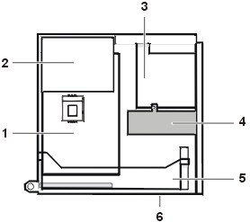
Figure 1 shows a side view of the mini tower chassis computer to help orient you when you work inside the computer.
Figure 1. Mini Tower Chassis Orientation View
 |
|
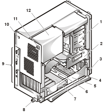
Figure 2 shows the mini tower chassis with the cover removed.
Figure 2. Inside the Mini Tower Chassis
 |
|
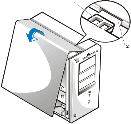
Figure 3. Computer Cover Removal
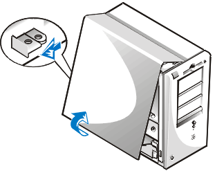 |
To remove the mini tower computer cover, perform the following steps:
 |
|
To replace the mini tower computer cover, perform the following steps:
Front Bezel
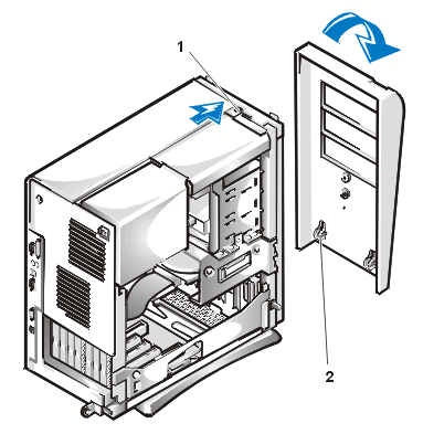
Figure 5. Front Bezel Removal
 |
|
To remove the front bezel, perform the following steps:
To replace the
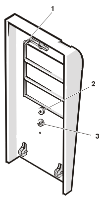
front bezel, perform the following steps:Figure 6. Eject, Power, and Reset Button Removal
 |
|
To remove the eject, power, and reset buttons, perform the following steps:
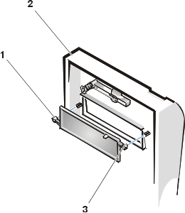
Figure 7. 5.25-Inch Front-Panel Insert Removal
 |
|
To remove a 5.25-inch
front-panel insert, perform the following steps:
To replace a 5.25-inch front-panel insert, position the two ring-tabs over the posts on
the inside of the bay opening, and then press the ring tabs over the posts.
Control Panel
 |
|
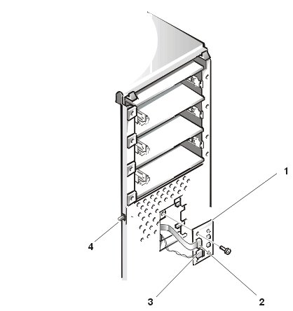
To remove the control panel, perform the following steps:
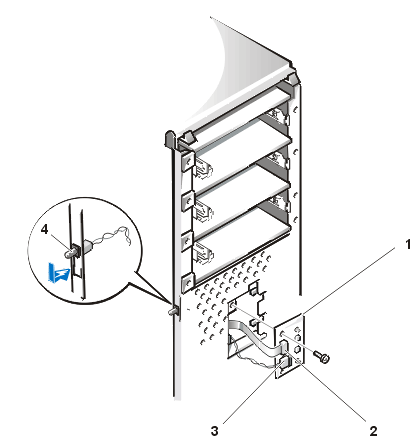
Figure 9. Chassis Intrusion Switch Removal
 |
|
To remove the chassis intrusion switch, perform the following steps:
 |
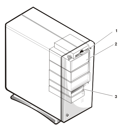
NOTE: In all of the following procedures, left and right refer to your left and right as you face the front of the computer. |
 |
|
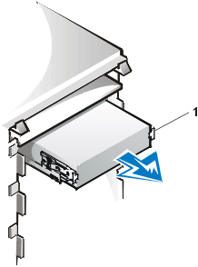
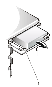
Figure 11. Removing a Diskette Drive From a Drive Bay
 |
|
To remove the 3.5-inch diskette drive from the drive bay, perform the following steps:
When you replace the 3.5-inch diskette drive, be sure that the two hooks on the right side of the bracket engage the mounting holes in the side of the 3.5-inch diskette drive.
Figure 12. Removing a 5.25-Inch Drive From a Drive Bay
|
To remove a 5.25-inch drive from a drive bay, perform the following steps.
|
NOTE: For easier access inside the chassis, you may want to rotate the power supply out of the way temporarily. |
To replace the 5.25-inch drive, perform the following steps:
Figure 13. Attaching the Drive Bracket to the New Drive
|
|
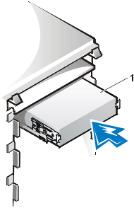
Make sure that both bracket tabs snap into place in the drive bay.
Figure 14. Inserting the New Drive Into the Drive Bay
 |
|
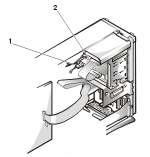
NOTICE: You must match the colored strip on the cable with pin 1 on the drive's interface connector to avoid possible damage to your system.
Figure 15. 5.25-Inch Drive Cables Attachment
 |
|
If your system came with an EIDE CD-ROM or tape drive, use the spare connector on the existing interface cable. Otherwise, use the EIDE interface cable provided in the drive kit.
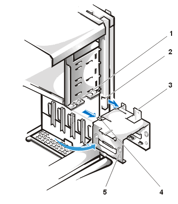
Figure 16. Hard-Disk Drive Bracket Removal
 |
|
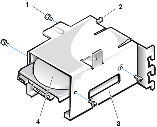
To remove a hard-disk drive from the mini tower's internal hard-disk drive bracket, perform the following steps.
|
CAUTION: To avoid the possibility of electric shock, turn off the computer and any peripherals, disconnect them from electrical outlets, and then wait at least 5 seconds before you remove the computer cover. Also, before you remove a drive, see the other precautions in "Precautionary Measures." |
Figure 17. Hard-Disk Drive Removal From Bracket
 |
|
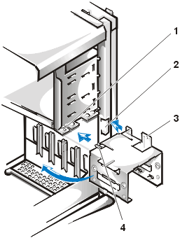
To install a replacement hard-disk drive, perform the following steps.
|
CAUTION: To avoid the possibility of electric shock, turn off the computer and any peripherals, disconnect them from electrical outlets, and then wait at least 5 seconds before you remove the computer cover. Also, before you install a drive, see the other precautions in "Precautionary Measures." |
NOTICE: To avoid possibly damaging the by electrostatic discharge (ESD), ground yourself by touching an unpainted metal surface on the back of the computer.
NOTICE: When you unpack the drive, do not set it on a hard surface, which may damage the drive. Instead, set the drive on a surface, such as a foam pad, that will sufficiently cushion it.
- If you are installing a drive in the 1.6-inch bay, use the four screw holes in the side of the bracket (see Figure 17).
Figure 18. Drive Bracket Insertion Into Chassis
 |
|
NOTICE: You must match the red-colored stripe on the EIDE cable with pin 1 on the drive's interface connector to avoid possible damage to your system.
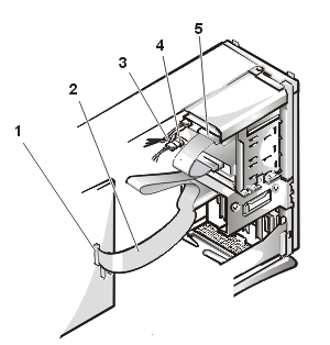
Figure 19. Hard-Disk Drive Cables Attachment
1 Blue interface connector (on EIDE1) 2 Interface cable 3 Power cable 4 Power input connector on drive 5 Interface connector on drive
NOTICE: You must match the blue connector on the interface cable to the EIDE1 connector on the system board to avoid possible damage to your system.
NOTICE: You must match the red-colored stripe on the EIDE cable with pin 1 on the IDE1 connector to avoid possible damage to your system.
See the documentation for your operating system for instructions.
NOTE: On systems with hard-disk drives larger than 2 GB, create a primary partition of 2 GB and divide the remaining capacity into partitions of 2 GB or less. For example, a system with a 2.5-GB hard-disk drive would have a primary partition of 2 GB (drive C) and a second partition of 500 MB (drive D). Hard-disk drives must be partitioned this way because MS-DOS®–based operating systems (including Microsoft® Windows NT®, when using a FAT16 file system) do not support drive partitions larger than 2 GB.
For instructions, refer to the documentation that came with your operating system.
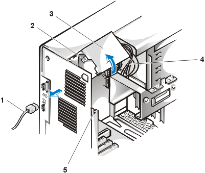
Figure 20. Power Supply Removal
 |
|
To remove the system power supply, perform the following steps:
| NOTICE: Use a wrist grounding strap as explained in "Precautionary Measures." |
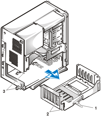
To remove the expansion-card cage, perform the following steps:
Figure 21. Expansion-Card Cage Removal
 |
|
To replace the expansion-card cage, perform the following steps:
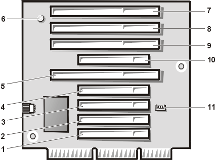
The mini tower chassis is available with either a PCI riser board (see
Figure 22) or a PCI/ISA riser board (see Figure 23). The PCI riser board provides five PCI expansion card slots. The PCI/ISA riser board provides three PCI expansion slots, two ISA expansion slots, and two shared PCI/ISA expansion slots.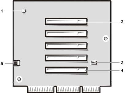 |
|
Figure 23. Mini Tower Chassis PCI/ISA Riser Board
 |
|
To remove a riser board, perform the following steps.
|
CAUTION: Use a wrist grounding strap as explained in "Precautionary Measures." |
NOTICE: To avoid possibly damaging expansion cards or the system board by electrostatic discharge (ESD), ground yourself by touching an unpainted metal surface on the back of the computer.
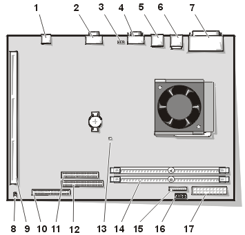
The subsections that follow contain procedures for locating or removing some of the system board components, which are shown in Figure 24.
Figure 24. System Board Components
 |
|
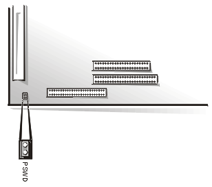
Figure 25 shows the location of the PSWD jumper on the system board.
Figure 25. System Board PSWD Jumper
 |
Jumper pins are small groups of two or more pins on a circuit board. Plastic jumpers containing a wire fit down over the pins. The wire connects the pins and creates a circuit.
NOTICE: Make sure your system is turned off before you change a jumper setting. Otherwise, damage to your system or unpredictable results may occur.
To change a jumper setting, pull the jumper off its pin(s) and carefully fit it down onto the pin(s) indicated.
Dell shipped your computer with a PSWD jumper installed, meaning that password features for this computer system are enabled. When you remove the jumper, or when you install the jumper on only one of the two pins, the password features for this computer system are disabled.
Table 1 lists the labels for connectors and sockets on your system board and gives a brief description of their functions.
Table 1. System Board Connectors and Sockets
| Connector or Socket | Description |
|---|---|
| AUX_LED | Auxiliary power indicator |
| B1 | Battery socket |
| DIMM_x | DIMM socket |
| DSKT | Diskette/tape drive interface connector |
| ENET | Integrated NIC connector |
| FAN | Microprocessor fan connector |
| IDEn | EIDE interface connector |
| KYBD | Keyboard connector |
| MICROPROCESSOR | Microprocessor connector |
| MONITOR | Video connector |
| MOUSE | Mouse connector |
| PANEL | Control panel connector |
| PARALLEL | Parallel port connector; sometimes referred to as LPT1 |
| POWER_1 | Main power input connector |
| POWER_2 | 3.3-volt V power input connector |
| RISER | Riser board connector |
| SERIALn | Serial port connectors |
| USB | USB connectors |
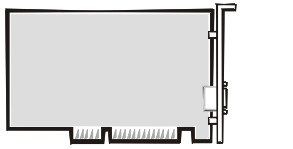
The mini tower GX100 chassis can accommodate up to five 32-bit PCI expansion cards. Figure 26 shows an example of a 32-bit PCI expansion card.
Figure 26. 32-Bit PCI Expansion Card Example
 |
|
CAUTION: Use a wrist grounding strap as explained in "Precautionary Measures." |
To remove an expansion card, perform the following steps:
|
NOTE: Installing filler brackets over empty card-slot openings is necessary to maintain Federal Communications Commission (FCC) certification of the system. The brackets also keep dust and dirt out of your computer. |
|
NOTE: After you remove and replace the
cover, the chassis intrusion detector will cause the following message to be displayed at
the next system start-up: ALERT! Cover was previously removed. |
See the online
System User's Guide for detailed instructions on the Intrusion detector. |
NOTE: If a setup password has been assigned by someone else, contact your network administrator for information on resetting the chassis intrusion detector. |
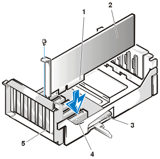
Figure 27. Expansion Card Installation
 |
|
|
CAUTION: Use a wrist grounding
strap as explained in "Precautionary
Measures." |
|
CAUTION: Some network cards automatically start up the system when they are connected. To guard against electrical shock, be sure to unplug your computer from its electrical outlet before installing any expansion cards. |
To install an expansion card, perform the following steps:
See the documentation that came with the expansion card for information on configuring the card, making internal connections, or otherwise customizing it for your system.
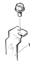
Save the screw to use when installing the expansion card later in this procedure.
Figure 28. Filler Bracket Removal
 |
|
|
NOTE: After you remove and replace the
cover, the chassis intrusion detector will cause the following message to be displayed at
the next system start-up: ALERT! Cover was previously removed. |
|
NOTE: If a setup password has been assigned by someone else, contact your network administrator for information on resetting the chassis intrusion detector. |
 |
|
|
CAUTION: Use a wrist grounding strap as explained in "Precautionary Measures." |
To remove a DIMM, perform the following steps:
To install a DIMM, press the DIMM fully into the socket while closing the ejectors to lock the DIMM into the socket (see Figure 30).
 |
|
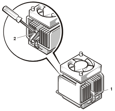
Figure 31. Microprocessor/Heat Sink Removal
 |
|
|
CAUTION: The microprocessor SEC cartridge/heat sink
assembly can get extremely hot. Be sure that the assembly has had sufficient time to cool
before you touch it. |
|
CAUTION: Use a wrist grounding strap as
explained in Precautionary Measures. |
|
NOTE: Dell recommends that only a technically
knowledgeable person perform this procedure. |
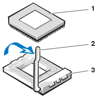
To replace a microprocessor, perform the following steps:
| NOTICE: Be careful not to bend any of the pins
when removing the microprocessor from its socket. Bending the pins can permanently damage
the microprocessor. |
Figure 32. Microprocessor Removal
 |
|
|
CAUTION: Ground yourself by touching an
unpainted metal surface on the back of the computer. |
| NOTICE: Be careful not to bend any of the pins when unpacking the microprocessor. Bending the pins can permanently damage the microprocessor. |
|
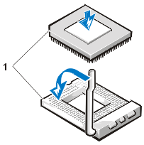
NOTE: Identifying the pin-1 corners is critical to positioning the chip correctly. |
Figure 33. Microprocessor Chip Installation
 |
|
|
CAUTION: Ground
yourself by touching an unpainted metal surface on the back of the computer. |
| NOTICE: Positioning the
microprocessor chip incorrectly in the socket can permanently damage the chip and the
computer when you turn on the system. |
| NOTICE: When placing the microprocessor chip
in the socket, be sure that all of the pins go into the corresponding holes on all sides
of the socket. Be careful not to bend the pins. |
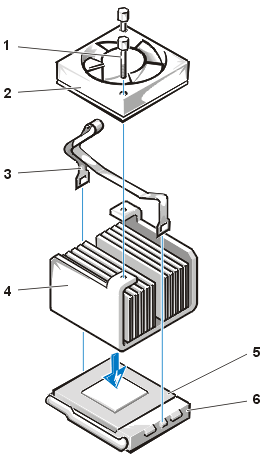
Figure 34. Heat Sink Installation
 |
|
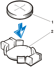
Figure 35. System Battery Removal
 |
|
|
CAUTION: There is a danger of the new battery exploding if it is incorrectly installed. Replace the battery only with the same or equivalent type recommended by the manufacturer. Discard used batteries according to the manufacturer’s instructions. |
To remove the system battery, perform the following steps:
When you replace the system battery, orient the new battery with the "+" facing up. Insert the battery into its socket and snap it into place.
Figure 36. System Board Removal
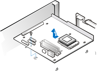 |
To remove the system board, perform the following steps:
If you are replacing a system board, remove the DIMMs and the microprocessor/heat sink assembly, and install them on the replacement board. Also, set the jumpers on the new system board so that they are identical to those on the old board, unless a microprocessor upgrade is being installed.
When you reinstall the system board, before you slide the system board back to lock it in position, push down near each slot to engage the grounding clip onto its corresponding tab. Push evenly on both sides of the system board as you slide it into position (do not twist the system board).